Monday, March 14, 2016

Soldering Tip Care


Tip maintenance of your soldering iron is a necessary action.  Without proper tip care your soldering days are greatly reduced and tip replacement comes sooner than expected. With high heat needed for soldering, especially for lead-free soldering, tip burnout is more likely to occur.  Temperatures of 700 – 750 degrees Fahrenheit for lead-free and 650 – 700 degrees Fahrenheit for tin/lead are not uncommon.  Some soldering stations are capable of reaching 900 degrees Fahrenheit. 

As you can see lead-free solder requires a much higher heat to melt.  Sometimes this leads to “cold tips” where the ends turn black and the solder fails to adhere to the tip surface. You may think the tips are not heating properly when the solder just balls up and falls off the ends.  But, don’t be fooled, this stuff is still hot and can burn you.  Shown below is an example of how some manufacturers have overcome the overheating problem.  This technology is built into the soldering tips that I prefer to use for my own jobs.


Smartheat Soldering Tips

With tips generally made with a soft copper core the outside is coated with some form of metal alloy such as iron.  Iron can withstand an immense amount of heat over a long period of time.  However, if the iron or other surface coating is damaged, such as scratching or bending, the tip will incur heat loss and the “cold tip” syndrome will commence.  Iron can also corrode causing dewetting. 

In order to prevent premature tip failure a few things can be done to negate this.  Turn the heat down! When not using the soldering station for five to ten minutes turn it off.  This will help in maintaining a longer tip life.  Most modern soldering stations can heat up and cool down within just a few seconds.  So, why not utilize this feature and save your tips from an early grave? Heat wears out tips. 
Next, make sure the tip is clean and tinned prior to placing it back in the holder.  Tips will wear out much quicker when not properly cleaned and tinned.  Lastly, use the proper cleaning tools for tip maintenance.  A battery terminal scraper is not the correct tool for cleaning soldering tips.

Another useful thing to remember is to keep your solder types separate.  Lead-free solder should never be used with a tip that is used for tin/lead RMA or non-rosin core solder.  When you mix solder types the layer of solder left on the tip from tinning will have a lasting affect every time you use the tip.  


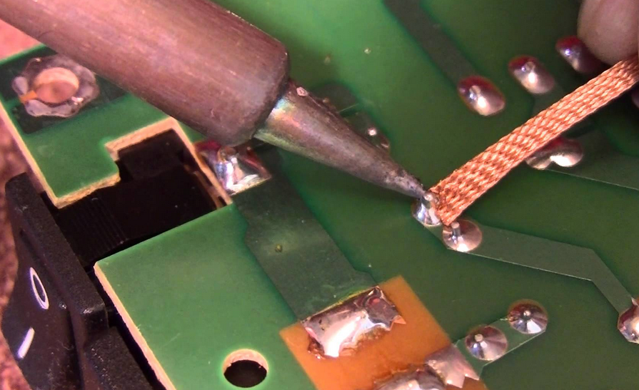
Example of the proper way to maintain soldering tips

Now, it’s not to say that you can’t use the same tip for each type of solder.  However, the extreme cleaning action needed to completely remove the tin/lead or lead free solder from the tip is harder to accomplish than just switching tips.  “Why not just keep tips separate for lead-free and tin/lead?  This would negate any problems down the line if you perform both types of soldering on a continuous basis.

Let’s take a look at maintaining a tip utilizing tin/lead solder.  Since tin/lead soldering is the most widely used method in electronics manufacturing I will cover that first. 

Before you start soldering, the tip of your iron should be cleaned of any residual solder, flux, or debris. Start by heating up the tip to its normal operating temperature that you have set.  Next, clean the tip on a sponge and then with some soft brass wool or “brass brillo” as we call it in the industry.  Ensure you use a cellulose sponge and not a synthetic sponge.  The synthetic types will melt when the tip comes in contact.  In addition, remember to use only deionized water.  Regular tap water has minerals that will shorten and damage the life of your tip.


Example of Brass Wool or "Brillo"

Make sure all solder has been removed.  Next, melt just a dab on the tip to prevent oxidation.  A dirty tip with no tinning will not conduct heat properly from the tip to the part to be soldered.  You can also use a burnishing tool if you don’t have access to a rotary cleaner or a can of tip tinner.  I don’t recommend using a burnishing or polishing tool unless you don’t have any other method of cleaning your tips.  Tip tinner works well for tips in removing burnt on flux and debris.  Just roll the heated tip around inside the tinning can until the black color turns to silver and you know then that it is clean.  Once cleaned, remove the excess tip tinner with the sponge and brass brillo.  Then re-apply solder to tin the tip properly.  Tip tinner is not meant to be left on the tip.  It is only for cleaning the tips and nothing else.


Example of Tip Tinner 
 
If you have cleaned the tip properly, and the solder has adhered to the tip while pre-tinning, then you have successfully cleaned the tip.  If the tip is not cleaned properly and the solder just balls up as you try to tin the tip, then more than likely it is still dirty or damaged. 

Never and I mean never, bend or dent the tips to another shape.  Never pull a tip out or install with a pair of pliers.  Soldering tips are meant to apply solder and not to be bent to a different shape.  If you need a 90 degree tip and only have a straight tip then spend the money and get the right tip.  When you bend a tip or damage it by yanking on it with pliers the tip becomes ineffective in completing the soldering job efficiently.  Heat transfer is lost due to the damage incurred. 

In some instances the sponge and brass wool become ineffective in cleaning your tips.  There are rotary motor driven tip cleaners that can remove more oxidation than normal cleaning can provide.  These units are a little more expensive than hand cleaning methods.  However, if you are a serious solder technician they are worth the cost.  I personally use one in my own lab on a monthly basis and they save time and money replacing expensive tips.


Example of a soldering tip polishing tool 
 
When using lead-free solder, cleaning and maintaining the tips are pretty much the same as with tin/lead tips.  However, temperature ratings are much higher for lead-free tip usage and therefore the tips tend to wear out much sooner.

So, when you decide to perform maintenance on your own tips remember to treat them gently.  A well maintained set of tips should last for a very long time.  I have tips that are over five years old and still perform as if they were bought just yesterday.

Wednesday, March 9, 2016

Surface Component Soldering


Surface mounted device or (SMD) soldering, consist of placing a component on a circuit board and soldering the device on to pads provided for the item.  Each component is sized and usually silk screened, for the appropriate placement on the circuit board.  


Example circuit board with surface mounted components


SMD components come in many sizes.  Some are smaller than a speck of dust.  Other's are as large as your hand.  Below is an illustration showing the different sizes as they relate to your hand.


Example of SMD component sizes

Now, when you decide to solder one of these devices on to your own circuit board you must first ask yourself, “what is the proper size and type of soldering tip I need?”  That’s a good question and we’ll go over that.

For example, if you are soldering a 0603 resistor you would definitely not need an 800 degree tip to perform this process.  I generally use a 600 to 650 degree chisel tip or bent conical for this action, depending on where the component needs to be installed.  If the resistor is easily accessible I will use the chisel tip.  If it is in a tight spot I might change to the slim bent conical to gain easy access. 
You will have to make your own decision on what type to use for your job as I can only make a suggestion based on my own experience as an IPC Specialist. 

Example of a 0603 SMD resistor

So, now that you have selected a tip it is time to solder that resistor to the board.  First off, clean the pads well with some isopropyl alcohol and an acid brush.  Dry the area thoroughly.  If you are using rosin core solder make sure to use rosin flux if you decide that you need more wetting action. 

Note: (you should never mix fluxes with the incorrect type of solder) i.e. do not use no-clean flux with a rosin core solder.  Consult your user’s manual before proceeding if unsure.

Place the component on the pad and position into place.  Ensure the resistor’s leads cover at least 75% of the pad area on each side.  Add some flux to the component.  Add a dab of solder to your tip and tack the component on one side to hold it in place.  Once tacked you can add more flux and then proceed to solder both sides. Don’t be afraid to use flux liberally if needed.

Once soldered the fillet should be shiny and concave on each side, (unless you are using lead-free solder).  If you used rosin core solder and rosin flux you must clean the area of residue.  If you have used no-clean flux and non-rosin core solder you may forego cleaning the area if desired.  I prefer to clean all of my solder jobs upon completion just to ensure that all debris and residue are removed.
Most SMD’s are soldered to a circuit board in this manner when a technician is hand soldering.   


Example video of proper way to solder an SMD resistor

There are machines that can do the work much quicker and are generally used for mass production of circuit boards.  I will cover those in future articles.  We will just cover the basics in this article to help get you started soldering SMD components to your own circuit boards.

Now that you have practiced a bit on a simple SMD resistor let’s move up to a multi-lead component such as an SOIC. 

Place the component on the appropriate pads and line up pin one of the component, usually designated with a dot or arrow, with the silk screen designation for pin one on the board.  It is usually a white dot at one corner.  Line up the leads and once again ensure that all of the leads cover at least 75% of their pads. 

Next, flux the leads and place a dab of solder on your tip.  I prefer to use a hoof tip for multi-leaded SOIC's.  Place a dab of solder on the bottom of the hoof tip and tack 2 corners of the component to hold it in place.  Now, take you hoof tip and drag it across 2 or 3 leads at a time.  You will see that the solder will flow up the leads and pads in a uniform manner.  If you get too much on the leads a solder bridge may be formed.  To remove the bridge just take your empty hoof tip and drag it down and away from the 2 leads.  If this doesn’t work use some wicking braid and then re-solder the affected leads.

Ensure that you don’t use too much solder.  The solder should not flow up the leads of the component past the halfway point.  Rather, the solder should flow over the pad and cover just enough of the component leads to adhere the component to the pad.  You should be able to make out the lead under the solder fillet.

In the video below the technician has chosen to use a bent conical tip for soldering his component into place.  This is perfectly acceptable.  There is no "one rule" for each specific job.  You must chose what works for your job in order to attain the best outcome.


Example video of the proper way to solder an SMD SOIC

Inspect the fillet for correct concavity and the lead for proper placement.  The fillet should be shiny and free of any pitting, cavities, or debris. Clean the area you just soldered well with isopropyl alcohol and a good stiff bristle brush, such as an esd safe acid brush. Dry everything thoroughly before placing back in a bag or equipment cavity.
 
There, now you’re almost an expert.  Keep practicing and try different tips.  I generally select a tip for my own jobs based on what works best for me.  You will learn how to select the right tips for each of your own job as you progress on your journey through the exciting world of soldering.

Thursday, March 3, 2016

Through Hole Soldering


Soldering a through-hole or axial lead component to a circuit board is not as hard as you might think.  The first thing to ask yourself is this, "do I know what I'm doing?"

If you answered yes, then you should proceed without reading any further.  If you answered no, then you might need to read this article.  Let's start with the assumption that you have very little or no skill at all in soldering a through-hole component to a circuit board.

Take the board below as an example.  When soldering a through-hole component to a circuit board you should ensure that the eyelets, or holes, should be free and clear of any solder or debris.  Use some isopropyl alcohol and clean the surfaces thoroughly.  If the eyelets have not been tinned then now is the time to do that.  Solder will flow better if the eyelets are tinned prior to soldering the component into the holes.  Ensure you don't use too much solder when you perform this task.  The eyelets should look similar to the ones on the right of the illustration below.  if they look like the ones on the left you have not used enough solder.  The eyelets in the middle need tinned.


Examples of tinned eyelets
 
Now that you have cleaned the holes, it's time to place your component into the appropriate spot.  If it's a multi-leaded component or similar, be sure that all of the leads are placed in their holes.  Once placed, turn the circuit board over and slightly bend the leads so the component will remain in place.  Some people prefer to leave them straight and use tape.  


 Axial or Through-Hole leads bent on PCB

While this method will work, I prefer not to use tape as it leaves residue on the components.  The industry standard is to bend the leads slightly on the backside and then solder them in.  Above you will see in the illustration the leads are slightly bent on the backside.  You can use either method.  The industry standard is generally to measure the leads on the backside, tack them in place, and then cut them to the appropriate height.  Once cut and tacked they can then be soldered.

Now that the leads are in place it's time to solder.  Add a little flux, "I prefer a little tacky flux", and then apply your hot iron.  Place the tip of you iron to one side of the lead and the solder to the other.  Once the lead heats up the solder should flow around the lead and leave a nice concave fillet like the one shown below. 


Through Hole Soldering Technique

Although, I don't recommend using more solder than is necessary as shown in the video.  You should not have to use a desoldering tool to achieve a nice fillet if you flow the solder right the first time.  If you follow this method below there should be no need of two tools to achieve a nice fillet around the lead.


Proper Way to Solder Axial Leads

The video shown above is the correct way to solder in axial lead components.  Inspect your board and compare it to the end product in the video.

If you've used too much solder it might create a cold solder joint.  If you've used too little solder the joint may be weak and could crack over time.  This can also cause a cold solder joint from lack of solder.  The ideal solder joint for a through hole component should be concave and shiny all the way around the lead.  The eyelet should be completely filled, but not filled to the point of overflowing onto the component side.  

Once you have completed the soldering process it's time to clean the fillet.  Use some isopropyl alcohol and then inspect the fillets for signs of pits, depressions, and too much or too little solder.  Practice a while and you will become an expert in no time.

Monday, February 22, 2016

Desoldering


So, you’ve learned to solder a couple of wires together and have practiced at soldering them to a circuit board or terminal.  But, you’re not happy with the outcome.  What to do? 

Well, now you’ll have to desolder the wires or component from their resting place and try again.  But, how do you desolder?  Let’s take a closer look and I will attempt to enlighten you on this pain “in the you know what”, procedure.  If you've soldered your wire to a terminal and the end result looks something like the examples below, then you need to desolder that sucker for sure and start over!


Examples of poorly soldered terminals

First things first - You have to decide what tool or tools to use to remove the soldered connection that you’ve just made or one that was made many moons ago by you or some other technician. 

Is the connection done professionally or is it a globby mess that just needs to be reworked?  No matter, you must decide how to tackle this job as you would any other.  Do you use a desolder sucker, desolder tip, wicking braid, or do you just heat it up and pull as hard as you can until the wire rips from its holding?

I hope you didn’t decide on the last method.  In my expert opinion, the best way to remove a connection from a PCB or through-hole terminal is with a desoldering gun. 

You can select different types of nozzle sizes for removing the solder.  These desoldering guns basically just heat up the solder as a regular soldering iron does.  Then you press a lever and the vacuum in the unit sucks up the molten solder and places it in a chamber.  No fuss, no muss. 


Desoldering Gun

When sucking up the molten solder you must be sure to hold the vacuum on for at least three seconds.  This allows all of the solder to reach the holding chamber.  If you release too soon the solder may fall back out through the  nozzle tip and glob your desolder site with melted solder.  Be sure to clean the nozzle before and after each use to ensure the tip remains oxidation free.  Just add a little dab of solder to the tip as you would a standard soldering tip and place it in the holder for the next job.

This system works well for most through-hole type solder jobs.  The nozzles can be selected to fit the soldered joint, thus ensuring that all of the solder is removed with one action of the desoldering gun.  Make sure that you don’t hold the nozzle on the joint for too long.  Just like soldering with a tip, if you overheat the joint damage may occur.  Below is an example video of the soldering gun I use in my own lab.


Desoldering a PCB

The next way of removing solder, and one that I have used many times, is solder wicking braid.  It is essentially copper braid on a spool.  Add a little flux to the wick and place the braid next to the joint or connection that you want to desolder.  Place the iron on the other side of the braid and watch as the wicking action soaks up the melted solder and displaces it on the braid.  


 Desoldering with Wicking Braid

This method works well for most jobs.  However, if the solder is thick and is stuck down inside an eyelet or via you may have a harder time using wicking braid.  In those cases I recommend sticking to the desoldering gun or maybe use some Chip Quik.  Chip Quik is a low temperature melting solder alloy that helps with removing stubborn solder connections.

Another way, not the way I prefer, is to use a mechanical solder sucker.  This tool is spring loaded and can suck up melted solder similar to the desoldering gun.  Just push the plunger mechanism down until it latches.  Place the desoldering tool nozzle next to the joint that you want to desolder.  Melt the solder and then push the release button.  This allows the spring to expand in the plunger and suck up the melted solder.  If done right, most of the time this works well with through-hole connections.

I don’t prefer to use mechanical solder suckers due to the static charge that can be generated when the plunger is released.  Static electricity can be very damaging to a circuit board if it is of a high enough charge.  You most likely will not encounter a problem with this happening on a home project.  However, if you work in the electronics industry you may want to avoid using this tool.


 Example Desoldering Pump

For surface mounted components you may want to use very small wicking braid, a hot air pencil, or a very small desoldering nozzle.  I have actually used a combination of both a hot air pencil and a soldering iron to remove stubborn solder joints such as ones that have been soldered with silver solder. 

Many small SMD components can be removed readily with a little bit of wick and some flux.  You can also use desoldering tweezers.  The tweezers heat up like a soldering iron.  Except in this case you have two irons that consist of tweezers.  They come in many shapes, temperature ratings, and sizes. 

Just add a little flux to your joint, heat the joint with the tweezers and under most circumstances the component will come right off.  Occasionally, you must employ  a pre-heater or extra heat on the joints of the component to remove it.  In those cases I recommend using a preheater.  I will discuss the uses of preheaters in another article.  


Example video of desoldering tweezers

So, hopefully this has helped you in selecting what best works for your own desoldering job.  Have fun and try not to burn anything!