One of the first things I learned to do when I was being
trained to solder was the proper way to tin and prepare wire for soldering. You may think this would be easy. However, even the most mundane of tasks,
including soldering wire, can be daunting if you don’t know how to do it
properly.
First off, are you using solid or stranded wire? Is the wire copper coated, zinc coated,
aluminum coated? The type of metal the
wire consists of makes a difference as well.
You don’t necessarily need to tin the ends of solid wire. Stranded wire on the other hand should be
pre-tinned prior to splicing, soldering to a circuit board, or attaching to a
terminal of some kind.
When tinning wire always ensure that you don’t allow the
solder to “wick” up under the insulation.
The solder should flow up the wire until it is about one wire diameter
from the insulation. This ensures that
you don’t damage the insulation.
Remember to use the appropriate type of flux when tinning your wire.
When you flow the solder up the wire ends do not touch the
solder directly to the soldering iron tip.
Add a small dab of solder to the clean tip first and then heat the
wire. As soon as the heat transfer
commences touch the solder to the opposite side of the wire away from the
tip. The heat from the tip and flux will
allow the solder to flow. Advance the
tip and solder up the wire end until you reach the recommended stopping point
just before the insulation.
I use a solder wick or heat wick just behind the area to be
tinned to prevent too much heat from entering the insulation. This is just a basic tool that attaches to
the wire like a small pair of tweezers.
Below is an example of a solder anti-wicking tool.
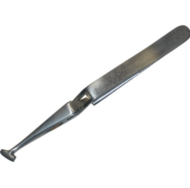
Anti-Wicking Tool
Now that you’ve tinned your wire end what do you do with it? Let’s see, are you attaching it to a board,
splicing it to another wire, or installing it into a terminal? Let’s cover the first one mentioned above.
When soldering a wire end into a circuit board there are
some different ways to do this. One way
is to solder the end into an eyelet.
First, place the appropriate size wire into the eyelet. If the wire is too large for the eyelet then
you are using the wrong gauge wire.
Cutting strands off the wire ends is not a recommended method of fitting
wires into eyelets or terminals. It is
actually a bad thing to do because you lose the current carrying properties
that were recommended for that size wire.
You could cause power and/or signal degradation by performing this
heinous act of hacking strands. And lastly,
you could cause the wire to be weakened at the end where it is soldered,
ultimately causing the wire to break off.

Example of soldered wires to a circuit board
In the example shown above you can see the wires have been soldered in correctly. However, the black wire exhibits some damage where it was held in place with a tool that created a heat bridge between the tool and the wire insulation. This could have been avoided if an anti-wicking tool had been used instead. You will also notice the eyelets are much larger than the diameter of the wire. This is perfectly acceptable if so designated in the electronics industry by an engineering drawing.
You will be fine as a home hobbyist to perform this action as well.
You will be fine as a home hobbyist to perform this action as well.
So you’ve found the correct size wire, have tinned the ends, and now are ready to solder into the eyelet. Place the wire into the eyelet with at least a half diameter wire size showing on each side of the eyelet. If you can only solder from one side of the board, that’s fine. Add some flux, add solder to your tip, and place the tip against the wire, then flow the solder on the other side of the heated wire. The solder should flow uniformly and not glob up due to inadequate heating. If you’re successful, the result should look something like the picture of the tinned wire on the right just below.

Example of the right way and the wrong way to tin a wire
Of course, you may not be soldering to an eyelet. Wires can also be soldered to component pads
and traces as well. If you want to learn
how to do this properly I suggest taking a course on soldering such as the IPC-7711/7721 rework system. I personally have
taken this course and it helped me to become a successful certified IPC specialist
in my field.
Another method of soldering your wire to a circuit board is
via a terminal. You can wrap the wire
around the terminal, through a terminal eye, or lay it through a channel. Then you solder the ends to that terminal for
a nice tight connection. Refer to IPC
7711/7721 for proper soldering techniques and acceptable criteria for soldering
to eyelets and terminals.
Example of soldering a wire to a terminal
The last method I want to cover here is wire splicing. There are several methods for accomplishing
this task utilizing soldering techniques.
The easiest way to splice a wire is with a lap splice. However, this
splice does not provide a lot of strain relief in and of itself. When creating a lap splice remember that both sides of the wire should be tinned at the same length. The wires should overlap by at least three
wire diameters and be parallel to each other.
You also have the option of adding a wire wrap around the splice for
added strength. After you have completed
the splice clean the wire and then cover the splice with heat shrink or other
material that will protect it from the environment or shorting to other
equipment.

Example of a properly spliced wire
Shown above is an example of a properly spliced Lap Splice. You will notice that the solder does not extend under the insulation, the wires do not exstend past the insulation, and the wire strands can still be clearly seen through the solder. Another item of notice is that the wires are laid parallel to each other with no gaps or solder globs.
Other methods of splicing wire include Mesh, Hook, Wrap, Western union, Rat-tail joint, and the Knotted tap. I'm sure that I may have missed one or two other's.
If you would
like a more in-depth breakdown on how to perform each type then refer to
IPC/WHMA-A-620B (Requirements and Acceptance for Cable and Wire Harness
Assemblies). Or, you can read up on
splicing at www.learn-about-electronics.com
in the soldering section.
No comments:
Post a Comment