Privacy Policy
We take your privacy seriously. This
policy describes what personal information we collect and how we use it.
(This privacy policy is applicable to websites falling under the
primary holder for TheSolderBlog.com).
Use of Pictures, Illustrations, and Video's
The use of pictures, illustrations, and video's used on The SolderBlog are meant for informational purposes only and do not garner any affiliate related advertising for profit for The SolderBlog.
Routine Information Collection
All web servers track basic information about their visitors. This
information includes, but is not limited to, IP addresses, browser
details, time stamps and referring pages. None of this information can
personally identify specific visitors to this site. The information is
tracked for routine administration and maintenance purposes, and lets me
know what pages and information are useful and helpful to visitors.
Cookies and Web Beacons
Where necessary, this site uses cookies to store information about a
visitor's preferences and history in order to better serve the visitor
and/or present the visitor with customized content.
Advertising
partners and other third parties may also use cookies, scripts and/or
web beacons to track visitors to our site in order to display
advertisements and other useful information. Such tracking is done
directly by the third parties through their own servers and is subject
to their own privacy policies.
Controlling Your Privacy
Note that you can change your browser settings to disable cookies if
you have privacy concerns. Disabling cookies for all sites is not
recommended as it may interfere with your use of some sites. The best
option is to disable or enable cookies on a per-site basis. Consult your
browser documentation for instructions on how to block cookies and
other tracking mechanisms.
Special Note About Google Advertising
Any advertisements served by Google, Inc., and affiliated companies may
be controlled using cookies. These cookies allow Google to display ads
based on your visits to this site and other sites that use Google
advertising services. Learn how to opt out of Google's cookie usage. As
mentioned above, any tracking done by Google through cookies and other
mechanisms is subject to Google's own privacy policies.
About
Google advertising: What is the DoubleClick DART cookie? The DoubleClick
DART cookie is used by Google in the ads served on publisher websites
displaying AdSense for content ads. When users visit an AdSense
publisher’s website and either view or click on an ad, a cookie may be
dropped on that end user’s browser. The data gathered from these cookies
will be used to help AdSense publishers better serve and manage the ads
on their site(s) and across the web. Users may opt out of the use of
the DART cookie by visiting the Google ad and content network privacy policy.
Some third-party avertisers used by Google may use a different cookie.
You may opt out of most-third party advertising cookies by following this link and visiting the Network Advertising Initiative opt-out page, or by visiting this Consumers page to opt out of all advertising cookies.
Contact Information
Concerns or questions about this privacy policy can be directed to The SolderBlog for further clarification.
Sunday, February 21, 2016

Saturday, February 20, 2016
Soldering Wires Together
One of the first things I learned to do when I was being
trained to solder was the proper way to tin and prepare wire for soldering. You may think this would be easy. However, even the most mundane of tasks,
including soldering wire, can be daunting if you don’t know how to do it
properly.
First off, are you using solid or stranded wire? Is the wire copper coated, zinc coated,
aluminum coated? The type of metal the
wire consists of makes a difference as well.
You don’t necessarily need to tin the ends of solid wire. Stranded wire on the other hand should be
pre-tinned prior to splicing, soldering to a circuit board, or attaching to a
terminal of some kind.
When tinning wire always ensure that you don’t allow the
solder to “wick” up under the insulation.
The solder should flow up the wire until it is about one wire diameter
from the insulation. This ensures that
you don’t damage the insulation.
Remember to use the appropriate type of flux when tinning your wire.
When you flow the solder up the wire ends do not touch the
solder directly to the soldering iron tip.
Add a small dab of solder to the clean tip first and then heat the
wire. As soon as the heat transfer
commences touch the solder to the opposite side of the wire away from the
tip. The heat from the tip and flux will
allow the solder to flow. Advance the
tip and solder up the wire end until you reach the recommended stopping point
just before the insulation.
I use a solder wick or heat wick just behind the area to be
tinned to prevent too much heat from entering the insulation. This is just a basic tool that attaches to
the wire like a small pair of tweezers.
Below is an example of a solder anti-wicking tool.
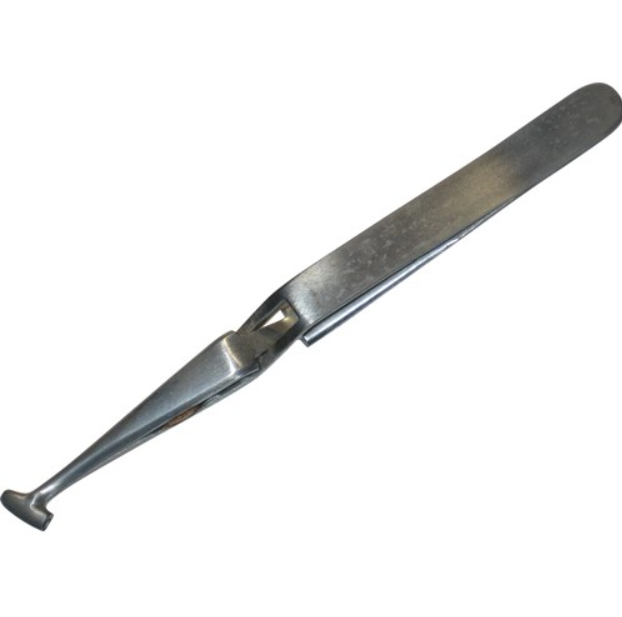
Anti-Wicking Tool
Now that you’ve tinned your wire end what do you do with it? Let’s see, are you attaching it to a board,
splicing it to another wire, or installing it into a terminal? Let’s cover the first one mentioned above.
When soldering a wire end into a circuit board there are
some different ways to do this. One way
is to solder the end into an eyelet.
First, place the appropriate size wire into the eyelet. If the wire is too large for the eyelet then
you are using the wrong gauge wire.
Cutting strands off the wire ends is not a recommended method of fitting
wires into eyelets or terminals. It is
actually a bad thing to do because you lose the current carrying properties
that were recommended for that size wire.
You could cause power and/or signal degradation by performing this
heinous act of hacking strands. And lastly,
you could cause the wire to be weakened at the end where it is soldered,
ultimately causing the wire to break off.

Example of soldered wires to a circuit board
In the example shown above you can see the wires have been soldered in correctly. However, the black wire exhibits some damage where it was held in place with a tool that created a heat bridge between the tool and the wire insulation. This could have been avoided if an anti-wicking tool had been used instead. You will also notice the eyelets are much larger than the diameter of the wire. This is perfectly acceptable if so designated in the electronics industry by an engineering drawing.
You will be fine as a home hobbyist to perform this action as well.
You will be fine as a home hobbyist to perform this action as well.
So you’ve found the correct size wire, have tinned the ends, and now are ready to solder into the eyelet. Place the wire into the eyelet with at least a half diameter wire size showing on each side of the eyelet. If you can only solder from one side of the board, that’s fine. Add some flux, add solder to your tip, and place the tip against the wire, then flow the solder on the other side of the heated wire. The solder should flow uniformly and not glob up due to inadequate heating. If you’re successful, the result should look something like the picture of the tinned wire on the right just below.

Example of the right way and the wrong way to tin a wire
Of course, you may not be soldering to an eyelet. Wires can also be soldered to component pads
and traces as well. If you want to learn
how to do this properly I suggest taking a course on soldering such as the IPC-7711/7721 rework system. I personally have
taken this course and it helped me to become a successful certified IPC specialist
in my field.
Another method of soldering your wire to a circuit board is
via a terminal. You can wrap the wire
around the terminal, through a terminal eye, or lay it through a channel. Then you solder the ends to that terminal for
a nice tight connection. Refer to IPC
7711/7721 for proper soldering techniques and acceptable criteria for soldering
to eyelets and terminals.
Example of soldering a wire to a terminal
The last method I want to cover here is wire splicing. There are several methods for accomplishing
this task utilizing soldering techniques.
The easiest way to splice a wire is with a lap splice. However, this
splice does not provide a lot of strain relief in and of itself. When creating a lap splice remember that both sides of the wire should be tinned at the same length. The wires should overlap by at least three
wire diameters and be parallel to each other.
You also have the option of adding a wire wrap around the splice for
added strength. After you have completed
the splice clean the wire and then cover the splice with heat shrink or other
material that will protect it from the environment or shorting to other
equipment.

Example of a properly spliced wire
Shown above is an example of a properly spliced Lap Splice. You will notice that the solder does not extend under the insulation, the wires do not exstend past the insulation, and the wire strands can still be clearly seen through the solder. Another item of notice is that the wires are laid parallel to each other with no gaps or solder globs.
Other methods of splicing wire include Mesh, Hook, Wrap, Western union, Rat-tail joint, and the Knotted tap. I'm sure that I may have missed one or two other's.
If you would
like a more in-depth breakdown on how to perform each type then refer to
IPC/WHMA-A-620B (Requirements and Acceptance for Cable and Wire Harness
Assemblies). Or, you can read up on
splicing at www.learn-about-electronics.com
in the soldering section.
Thursday, February 18, 2016
Lead Free Solder
So, you’re wondering if lead-free solder would be the best
choice for your project. You want to be environmentally friendly and think
using lead-free solder would be a big help. Woe is to the technician that loves the
lead-free realm! Let’s take a closer
look and I’ll explain why lead-free isn’t all that it’s cracked up to be in the
world of electronics.
First of all, lead-free solder was not the idea of any
technician that I know, have known, or have heard of in my thirty years in the
electronics industry. The European Union Electrical Waste and Electronic Equipment, or (WEEE), “yes, it has that
acronym”, and Restriction of Hazardous Substances Directive or (RoHS), came
into effect prohibiting the inclusion of large quantities of lead in almost all
consumer electronics produced in Europe.
Most manufacturers in the U.S. still use tin/lead
solder. Some may receive a tax break if
they reduce the lead content in their formulations.
Lead-free solders on the commercial market may contain some amount of tin, copper, silver, bismuth, indium, zinc, antimony, and small amounts of other trace metals.
Lead-free solders on the commercial market may contain some amount of tin, copper, silver, bismuth, indium, zinc, antimony, and small amounts of other trace metals.
Most lead-free solders have a much higher melting point than
conventional lead based solders with tin.
The temperature difference may be as much as 20 degrees Celsius higher
in some formulations.
Lead-free solder poses a unique challenge to the technician or manufacturer of electronic components when using lead-free solder. Solder pots and wave soldering machines must remain completely free of any tin/lead solder due to the contamination that the lead will introduce to the lead-free environment. Solder pots can literally blow out their sides when tin/lead and lead-free solders are mixed.
When using lead-free solder you may notice that the
resulting joint does not display a shiny appearance as the tin/lead solder
will. You should observe a dull, grainy
appearance after the joint has cooled and has been cleaned. This is normal in lead-free soldering. When using lead-free solder the solder tip
must remain completely clean and uncontaminated from any tin/lead solder. A small amount of lead-free solder must be
placed on the unused tip to reduce extreme oxidation caused by the lack of lead
in the solder.

Example of a lead-free soldered joint
Tin/lead solders were initially introduced to help prevent
the effects of “whiskering”. This is a
phenomenon caused by the tin in the solder.
Tin will actually grow tiny fine little whiskers over time if left
unchecked and can cause short circuits in electronics. Lead-free solders have this potential for
causing whiskering. Shown below is an example of this phenomenon under a microscope magnified many times.

Lead-Free solder whiskering
I prefer to stick with my tried and true tin/lead
solder. Unless you decide to move to
Europe in the near future, I recommend that you stick with standard solder and
leave worrying about the environment to the solder illiterate out there in the
world. They may never know what we go
through to ensure their electronics function properly the first time and
continue to function for many years.
Lead-free solder is a fine concept. However, in actual applications it’s not as
reliable as we would like it to be.
Lead-free soldered joints have a tendency to crack under stress and
loads. They don’t provide high
reliability in most aviation and medical applications either. That’s why we use tin/lead formulations in
most of our electronics in the U.S. and other non RoHS compliant nations.
But, if you’re dead-set on using lead-free solder in your own applications, I highly recommend that you do thorough research and get trained up on how to use this solder the correct way. Mixing your lead-free solder with tin/lead solder on a circuit board may have unwarranted effects in the long run.
Shown below is an example of the differences between tin/lead and lead free. You will notice that the joint on the left is shiny and smooth while the one on the right is dull and grainy. The shiny one is tin/lead and the dull one is obviously lead-free.

Comparison of tin/lead to lead-free
If you mix lead-free with tin/lead solder you may cause more damage soldering the
components to the board than the initial damage that caused you to rework the
circuits in the first place.
Take care and good luck on your lead-free journey if you so
choose this dangerous and windy path.
Wednesday, February 17, 2016
Solder
So, you’ve selected your soldering system, have your tips on hand, learned a little about what flux to use, and now you’re asking what type of solder would be best for your own project or needs. “That’s a very good question.” Let’s see if I can shed some light on this.
First of all let’s go over what solder is made from and then we’ll work on what you may need.
Solder is basically a filler material for soldering parts together. We will only cover electronic applications as there are other types of solder alloys for use in jewelry making, brazing pipes, and many other industries outside of electronics.
Solder is available in many alloys for differing applications. In electronics, the alloy or “Eutectic alloy”, of 63% tin and 37% lead (or 60/40) which is close or almost the same in its melting point, has always been the choice that most technicians prefer. “I use this mix on a daily basis in my own lab.”
This mix of tin and lead has its advantages. When the solder is heated to its melting point the solder will flow smoothly at its lowest temperature. This prevents the solder from going through what is known as the “plastic phase”. Having the lowest possible melting point prevents heat stress to electronic components. With little to no heat stress this prevents possible cracking of the electronic components. With no “plastic phase” present this allows for quicker wetting as the parts heat up and faster setup times as the solder cools.

Solder in roll form
Any “non-eutectic” formulations of solder, like lead-free solder, can result in unreliable joints if the parts don’t remain still during the soldering process.
Some common formulations for solder that I use and have used in my own lab are shown below.
63/37 – This melts at around at 183 Degrees Celcius or 361 Degrees Fahrenheit (eutectic: the only mixture that melts at a point, instead of over a range)
60/40 – This melts around 183-190 Degrees Celcius or 361-374 Fahrenheit
50/50 – This melts around 183-215 Degrees Celcius or 361-419 Degrees Fahrenheit
So, as you can see the different mixes of solder generally melt within similar temperature ranges. There are not a lot of differences in the formulations.
Some solders don’t contain lead at all. These “lead-free” solders are more widely used in countries that adhere to lead-free restrictions for electronics or rather (RoHS) or “Restriction of Hazardous Substance Directive.” This directive mostly covers European Countries and is not widely used in the United States or elsewhere.
These lead free solder formulations were introduced in an attempt to lower the use of lead in the electronics industry. It was thought that by using lead free solder the amount of lead that found its way into landfills, toys, and groundwater from discarded electronic devices would or could be reduced. Unfortunately, for the electronics industry, the use of lead-free solder alloys has made it difficult to produce quality electronic devices. Lead free solder does not contain any eutectic formulations. This type of solder melts at around 250 Degrees Celsius or 482 Degrees Fahrenheit. This high temperature needed to melt the solder makes it very difficult to create a reliable joint.
Some other common solders include low temperature formulations. Some of these alloys contain “Bismuth”.
One type I use to help remove stubborn circuit board components is called “Chip Quik”. This solder alloy melts at a very low temperature and is available in leaded and lead free formulations.
One type I use to help remove stubborn circuit board components is called “Chip Quik”. This solder alloy melts at a very low temperature and is available in leaded and lead free formulations.
Here is a quick video on how Chip Quik works
Some solders melt at a much higher temperature. One such solder is “silver solder”. This alloy is used where high strength joints are desired where common solders will just not work. Silver solder is also used to solder assemblies that you don’t want to become unsoldered during rework of surrounding components. There are also specialty solder formulations for soldering aluminum components.
Solder comes in many forms as well. The most common method of using solder is on rolls. However, there are also bars and paste solder. I purchase bar solder for my lab solder pots. This is an actual heating pot made specifically for melting solder. I use one when I have many wire ends to tin or leads that need tinned on a large scale. You may want one for your own use if you solder and need to frequently tin wire ends or leads.
Solder sizes are as varied as there are types, from the very small of just .010” to the larger .125” for common rolls. You can purchase bars as well in leaded and lead-free formulations.
Solder wire also comes in some of these common formulations:
(10/88/2), (60/40), (62/36/02), (62/36/2), (63/37), (Classic Tin/Lead), (Sn60),( Sn62), and (Sn63/Pb37)
For a complete breakdown of each designation, refer to the manufactures specifications. Solder can also come with no flux core or be manufactured containing no-clean, rosin, mildly activated rosin, water soluble, Glow core no-clean, or activated Rosin.
Refer to my article on flux for more information on fluxes and how they work.
Refer to my article on flux for more information on fluxes and how they work.
The last type of solder I want to cover is “solder paste”. Solder paste is a mixture of solder powder and flux. The flux acts as a tacky, viscous binding agent to help hold the solder in place as it is melted. The wetting action of the flux as it’s heated helps to flow the solder. This type of solder is used mostly for BGA and LBGA solder ball applications. To put in laymen’s terms, it’s used for the types of chips you would find on a computer circuit board that has no physical leads showing. The solder pads are hidden underneath the component. Usually manufacturers utilize stencils when using solder paste. However, you can use solder paste on your own project if you follow the example shown below.
Simple video showing how to use solder paste
I personally do not like using solder paste. The small solder balls mixed in the flux have a tendency to roam if not heated properly. You’re more susceptible to solder bridges and getting solder under the leads. So, I say stick to standard tin/lead solder for your home projects.
Selecting the right size will be up to you. I generally use a solder gage that is small enough to fit the size of the wire or component pad. Anything larger and you risk using too much. This usually results in a large glob of solder on the worked item. I use .010 for soldering extremely small components such as a 0402 or 0603 SMD (surface mount device). .015 works well for 0805 to 1206 SMD components. For tinning wire I either use the solder pot for multitudes, or start at .025 and work my way up from there depending on the wire size.
Whatever you use will ultimately be up to what you decide works best for your own project. What I have presented to you in this article should help lay a good foundation for your own soldering selection and experience.
Tuesday, February 16, 2016
Soldering Flux
Flux, what is it and why do we need to use it? Basically, the purpose of flux is to help facilitate
the soldering process by helping the solder to flow and preventing the
introduction of oxides. One problem that
we all will encounter when soldering are the introduction of impurities found
at the site of the solder joint.
Examples would be dirt, oil, or oxidation.

Example of Flux
Flux is your friend.
Always remember that short blurb when you are trying to solder
something. Attempting to solder without
flux by attacking the part with a dry tip is folly. You will not achieve a solid, clean joint,
free of impurities, dirt, and/or oxidation.
Flux helps prevent re-oxidation of the solder at the joint
by allowing the solder to flow before re-solidifying. If you use a dirty or partially cleaned tip
and no flux, the solder will melt, “somewhat”.
However, the solder will not flow
into the joint very well and the parts will not be connected properly. This usually results in a “cold” solder
joint. The result of this poor
connection will usually be high resistance and low to no current flow.
In a previous article about soldering tips I mentioned
something called “wetting”. I will
attempt to explain this phenomenon in more detail.
Basically, wetting allows the surface tension of the melted
solder to flow more easily. This helps
the solder to fill the joints between the parts to be soldered and the pad, or
wire that you are soldering to. To
precipitate or allow this “wetting” action to take place you need “Flux”.
Flux has been around the soldering industry for many
years. One of the earliest known
materials for flux was charcoal. It was
non-corrosive and non-conductive. It
acted like a reducing agent and helped prevent oxidation.
“Pine Tar” was another type of flux used in soldering. This was used because it had a “rosin-base”
and was ideal for soldering with soft solder.
It was non-corrosive and non-conductive at normal temperatures. But, when you heated the flux for soldering
to higher temperatures it was mildly corrosive and reactive. Some fluxes actually help with the cleaning
process as they heat up. This helps
prevent oxidation as the soldering process commences.
You also have the choice of using rosin-based or non-rosin
based solder. Many solder alloys on the
market today employ some sort of flux manufactured right into the core of the
solder itself. This helps the wetting
action as you solder by supplying the flux right from the core. No external flux is required.
There are three basic types of flux:
1.
Water Soluble – You can remove the active flux
from these from your soldered joint with just water. (no VOC’s are required)
1.
No-Clean Fluxes – This means that you don’t have
to clean the part after using this flux.
The residue left behind is non-corrosive and only needs to be cleaned if
it affects connections or causes undue contamination due to excessive wetness
in the areas that were soldered.
1.
Rosin Fluxes – These come in non-activated (R),
mildly activated (RMA), and activated (RA) types. RA and RMA are both forms of activated flux
with various levels of a wetting agent, typically some form of acid that
increases the wetting action of the parts to be soldered by removing the
oxides.
RA flux is corrosive and should be cleaned upon completion
of the soldering action. RMA is not as
corrosive as the RA flux. However,
cleaning is preferred to prevent any contamination to the joint after
soldering. You should never use an acid
based flux on electronic circuits. Acid
fluxes are best kept for use on brass and copper piping in the plumbing
industry. Damage to the circuit board
and components can be irreversible.
I clean all of the soldered joints that I make just so I
know that all corrosive fluids or contamination is removed. Whether I’m using no-clean, RA, or RMA, I
always clean my joints with a little isopropyl alcohol. 99% is preferred by most technicians.
Flux also comes in different forms. There is tacky flux, liquid flux, and flux in
paste form. Some types of fluxes require
them to be thinned down with flux thinner.
For this application I suggest referring to the manufactures
instructions.
There are many different flux applicators and containers as
well. There are flux pens, flux squeeze
dispensers, flux bottles, and tacky flux in syringes. Flux can also be purchased in gallon
containers and larger if your needs dictate a use of flux on a production
level.
It is a good practice to get into the habit of “not” mixing
fluxes together. If you are using
no-clean flux then you should not mix this with a rosin based solder. Always use “like agents” with their
partner. i.e. Rosin based fluxes should
be used with rosin core solders. You
should use no-clean flux with non-rosin core solder. Mixing fluxes can cause unwanted results from
the interaction of the solder and the flux at the joint. You may encounter poorly soldered joints, unwarranted
corrosion, maybe even overheating or cracking of the metal.
You will find that soldering without flux will make your job
much harder. Quality will suffer and any
soldered joints that look fine will most undoubtedly be inferior.
You should also consider utilizing a good flux remover if
you’re not satisfied with using isopropyl alcohol. There are several on the market and each has
a specific use. Check with the
manufactures instruction on how to use a particular flux remover. These special flux removers can be used to
take off no-clean, rosin, synthetic, and paste fluxes from most electronic
circuit boards.
Remember to always practice good safety when handling any
fluxes, thinners, solvents, and molten solder.
It’s very easy to forget that you can be burned, blinded, or irritated
by contact with anything related to your soldering project.
So, get that flux and put it to good use. “Remember “Flux is your friend”.
Subscribe to:
Posts (Atom)